Tuesday, November 12, 2013

Ultrasonic Welding Horn Design FEA

Topic: Improving 20 kHz Titanium Ultrasonic Welding Horn Design using FEA Finite Element Analysis

Industrial Ultrasonics, Inc was contacted by a major mattress manufacturer who was experiencing issues with their ultrasonic welding application (sealing non-woven material for individually wrapped coil spring mattresses). The two main issues were: 1) Uneven amplitude across the face of the horn was causing a weak weld at both ends of the seal area and 2) The horns were cracking and had to be replaced at an unacceptable rate of 7 or more per year.  Note: The ultrasonic horns that were giving the mattress manufacturer problems were being purchased directly from the OEM which supplied their ultrasonic welding equipment.

Our customer's existing horn design was analyzed using FEA (Finite Element Analysis) software.  As you can see in Figure 1 - Original Horn, there is adequate amplitude in the center portion of the working face (as represented by the dark red area), but the amplitude decreases at either end of the working face (as represented by the light red & pink areas).

Figure 1 - Original Ultrasonic Horn

The ultrasonic horn was redesigned utilizing FEA design software.  As you can see in Figure 2 - Redesigned Ultrasonic Horn, the amplitude is now evenly distributed across the entire face.  Also, the stress was reduced by 21% in the areas where the horns had typically been cracking.

Figure 2 - Redesigned Ultrasonic Horn
Industrial Ultrasonics, Inc began manufacturing the redesigned horns for the mattress manufacturer in December of 2010.  Nearly three years and many horns later, only one of these ultrasonic horns has cracked.

In addition to the huge savings experienced via reduced tooling costs and down time, the mattress manufacture was also able to increase production due to reduced weld cycle times.

Disclaimer: Keith Anderson of Industrial Ultrasonics, Inc designs and manufactures ultrasonic welding horns for use on all brands of ultrasonic welders including, but not limited to, Branson, Dukane, Forward Technologies, Herrmann, Rinco, Sonobond, and Stapla.  Please visit us at www.industrialultrasonics.com for more information.

Ultrasonic Horn Repair / Refurbish / Rework

We were contacted by a prospective customer who was having issues with their 20 kHz ultrasonic welding application (ultrasonically welding clamshells for pliers).  Their welder had begun overloading / faulting out and would no longer complete a weld cycle.  They asked if we worked on ultrasonic tooling that had been built by someone else and our answer was "absolutely".

20 kHz ultrasonic welding horn
as received from our customer
They sent their tooling to Industrial Ultrasonics, Inc for evaluation and it was determined that the aluminum back driver had cracked and needed to be replaced.  We informed our customer that the three titanium front drivers were still functional, but the face details were heavily worn and/or damaged.  Furthermore, the steel anvils on their fixture were also heavily worn and/or damaged.

Our quote for this project included: Build a redesigned 20 kHz aluminum back driver, reface and retune the three existing 20 kHz titanium front drivers, and reface the three steel anvils on the fixture.

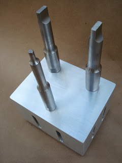
We received the order for this project. Once the various components were ready, the three refurbished titanium front drivers were attached to the new aluminum back driver, the steel anvils were mounted back onto our customer's original base plate, and our customer was back in production.

New aluminum back driver w/
three refurbished titanium front drivers.
Industrial Ultrasonics, Inc was able to save our new customer $1,576.00 by utilizing their existing titanium front drivers and fixture, and only replacing the aluminum back driver.  Since this initial order, we have performed similar services on multiple sets of ultrasonic tooling for this customer. 

Tooling ready to ship back to customer

Friday, May 31, 2013

How to tune an ultrasonic welding horn

There are several methods available for tuning an ultrasonic welding horn.  Ultrasonic horn manufactures rely upon frequency analyzers to measure the frequency of the ultrasonic horns during the manufacturing process.

CAUTION: Because multiple modes of vibration are present in all tooling, it is very important that the ultrasonic horn is tuned to operate on the correct axial frequency.  Tuning an ultrasonic horn to an incorrect non-axial frequency can result in catastrophic failure of the ultrasonic horn and/or damage to another component of the ultrasonic system (booster, converter/transducer, power supply, etc).

The most common method for tuning an ultrasonic horn is to build a "blank" horn with a tuned length that is .250"-.500" longer than the expected final tuned length (this results in a frequency which is lower than your target frequency).  Material is then removed from the working face of the horn, thus raising the frequency of the ultrasonic horn until the proper frequency is achieved.  The anticipated tuned length of an ultrasonic horn can usually be accurately achieved with proper use of FEA software.

Another common method for tuning an ultrasonic horn is to adjust the location of the radius "step" that is present on many ultrasonic horns, both circular and rectangular.  This method is commonly used when building multiple ultrasonic horns which require the same final tuned length.

Although not as common, the frequency can also be raised by removing material from the surface of the horn on which the stud is located.

On slotted horns, adjusting the slots will also affect the frequency of the horn but this is typically reserved for optimizing the performance of the ultrasonic horn rather than trying to simply adjust the frequency.

One of Industrial Ultrasonics, Inc cost saving services includes re-facing and re-tuning our customers' existing ultrasonic horns once the working surface has become worn or damaged.  If you are a customer with in-house machining capabilities, we can further increase your savings by advising you as to how much material can be removed from the face of the ultrasonic horn before it would need to be returned to Industrial Ultrasonics, Inc for re-tuning.

Disclaimer: Keith Anderson of Industrial Ultrasonics, Inc designs and manufactures ultrasonic welding horns for use on all brands of ultrasonic welders including, but not limited to, Branson, Dukane, Forward Technologies, Herrmann, Rinco, Sonobond, and Stapla.


Information required for quoting and designing an ultrasonic welding horn

If you are in need of a quote for an ultrasonic welding horn for a new application, here are a few key pieces of information that will be required by an ultrasonic horn manufacturer in order to provide you with an accurate quotation for the ultrasonic tooling:

  • Part Material - What is the material composition of the part that is to be assembled (ABS, PC, etc)?
  • Material Color - What is the color of the material (black, white, clear, light vs dark, etc)?
  • Quantity - How many parts do you anticipate producing (monthly, annually, life time, etc)?
  • Part print / file - Do you have a print and/or 2D/3D CAD file of your part?
  • Frequency - What is the operating frequency of the ultrasonic welder that the ultrasonic horn will be used on (15 kHz, 20 kHz, 35 kHz, 40 kHz, etc)?
  • Welder Information - What is the make and model of the welder that the ultrasonic horn will be used with (Herrmann, Branson, Dukane, etc)?
  • Stud Size - What stud size is required to connect the ultrasonic horn to your booster (3/8-24, 1/2-20, M8x1.25, M10x1.5, M12x1.25, etc)?
Depending upon the complexity of the application, more information may be required by the ultrasonic horn manufacturer but supplying the above information is a great place to start.

Keith Anderson, President
Industrial Ultrasonics, Inc
www.industrialultrasonics.com